The Shader Sorcery: Real-Time Rendering Techniques in Demoscene Productions
The demoscene is a realm where art, code, and raw computational power collide. For decades, demosceners have been at the vanguard of real-time graphics, pushing hardware to its absolute limits to craft breathtaking audiovisual experiences. In this pursuit, a suite of sophisticated rendering techniques has become indispensable, transforming raw geometry into vibrant, believable, and often otherworldly visuals. From the subtle nuances of light interaction to the dramatic flair of lens effects, these techniques are the secret sauce behind the demoscene’s enduring magic. Join us at MattCurrent.org as we delve into the core real-time rendering methods that define the cutting edge of demoscene aesthetics in 2026.
The Foundation: Real-time Rendering and the Demoscene Ethos
At its heart, the demoscene is a celebration of real-time rendering. Unlike pre-rendered animations, demoscene productions generate every frame on the fly, demanding immense efficiency and ingenuity from their creators. This ethos of constraint-driven creativity has historically led to groundbreaking optimizations and novel approaches to visual fidelity, often years before they become mainstream in commercial games. The goal is always to maximize visual impact within strict limitations—be it a 64-kilobyte executable or a 4-kilobyte masterpiece.
For instance, early demoscene titans like Future Crew’s “Second Reality” (1993) on the Amiga or more recent 4k entries leveraging modern GPUs, such as “Elevated” by Rgba (2009), showcased complex 3D scenes and effects that defied their minuscule sizes. These productions were, and continue to be, masterclasses in procedural generation and highly optimized shader programming. In 2026, while hardware has advanced exponentially, the core challenge remains: how to achieve the most stunning visuals with the least amount of data and computational overhead.
Modern demosceners harness the power of programmable shader pipelines (GLSL for OpenGL, HLSL for DirectX) to implement a vast array of effects. These shaders, small programs executed on the GPU for every pixel or vertex, are the building blocks of visual realism. They allow for intricate lighting, reflections, and post-processing, transforming a bare geometric scene into a rich, immersive environment. The techniques we’re about to explore are not just about mimicking reality; they are about crafting a compelling visual narrative that resonates with the demoscene’s unique blend of technical prowess and artistic expression.
Illuminating Realism: Ambient Occlusion and Shadow Mapping
Achieving visual realism hinges on how light interacts with objects. Two fundamental techniques, Ambient Occlusion and Shadow Mapping, are critical for grounding objects in a scene and adding depth, making them feel like they truly belong in their environment rather than floating in space.
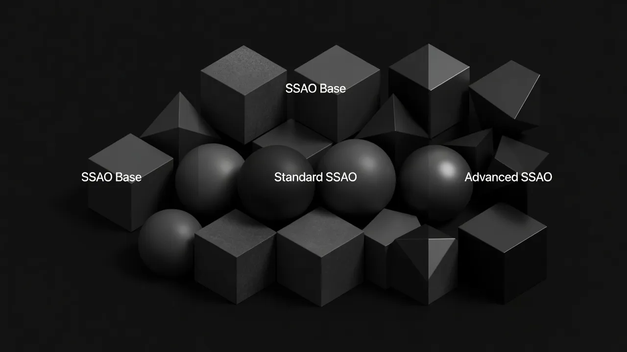
Ambient Occlusion (AO) is a technique that simulates the subtle, soft shadows caused by ambient light being blocked by nearby surfaces. Unlike direct lighting, which casts sharp, directional shadows, AO accounts for the overall “darkening” in crevices, corners, and areas where objects are close together. This seemingly minor detail dramatically enhances the perception of depth and contact between objects. Without AO, scenes can look flat and artificial, as if objects are merely painted onto a backdrop.
The most common real-time variant in demoscene and games is Screen Space Ambient Occlusion (SSAO). Introduced by Crytek in 2007, SSAO approximates ambient occlusion by sampling depth values from the current screen buffer. For each pixel, it queries its surrounding neighbors in screen space, and if those neighbors are closer to the camera, it implies an obstruction, thus darkening the pixel. While highly efficient, SSAO can suffer from artifacts like “haloes” or flickering, especially at screen edges. Demosceners often employ highly optimized or simplified SSAO variants to fit within performance and size budgets, sometimes even resorting to clever texture-based pre-computed AO for static elements. For example, a 4k demo might use a very coarse SSAO kernel or even bake subtle occlusion into vertex colors for key objects to save shader complexity.
Shadow Mapping, on the other hand, is the cornerstone for rendering hard and soft shadows cast by direct light sources. The concept, first proposed by Lance Williams in 1978, is elegantly simple:
- Render the scene from the perspective of the light source, storing only the depth of the closest surface into a “shadow map” texture.
- When rendering the scene from the camera’s perspective, for each pixel, transform its world-space position into the light’s space.
- Compare this transformed position’s depth with the corresponding depth stored in the shadow map. If the pixel’s depth is greater than the shadow map’s depth, it means there’s an object closer to the light, and thus the pixel is in shadow.
Every technique in this guide ultimately runs as a shader — our introduction to shader programming as the foundation of real-time rendering builds the prerequisite skills.
Shadow mapping introduces several challenges, primarily aliasing (jagged shadow edges) due to the finite resolution of the shadow map. Techniques like Percentage-Closer Filtering (PCF) or Variance Shadow Maps (VSM) are commonly used to smooth these edges, creating more realistic soft shadows. For large scenes, Cascaded Shadow Maps (CSM) are often employed, using multiple shadow maps at different resolutions to cover varying distances from the camera. Demoscenes frequently use shadow mapping to add dramatic contrast and realism, especially in scenes with dynamic lighting. A typical demo might feature a single directional light with a high-resolution shadow map, perhaps with PCF, to ensure crisp shadows from key moving elements like characters or vehicles, making them feel physically present in the environment.
// Simplified Shadow Map Check in a fragment shader
vec3 lightDir = normalize(lightPos - worldPos);
vec4 shadowCoord = lightSpaceMatrix * vec4(worldPos, 1.0);
vec3 projCoords = shadowCoord.xyz / shadowCoord.w;
projCoords = projCoords * 0.5 + 0.5; // Transform to [0,1] range

float currentDepth = projCoords.z;
float shadowMapDepth = texture(shadowMap, projCoords.xy).r;

float shadow = (currentDepth > shadowMapDepth) ? 0.0 : 1.0;
// Add bias and PCF for better results
These two techniques, often working in tandem, are fundamental to creating believable lighting and spatial relationships, transforming abstract geometry into tangible worlds within the demoscene.
Beyond the Lens: Bloom and Tone Mapping
While ambient occlusion and shadow mapping ground objects in reality, bloom and tone mapping elevate the scene’s aesthetic, mimicking the optical properties of real-world cameras and enhancing the overall visual drama. They are crucial for achieving that polished, cinematic look often seen in high-end demoscene productions.
Bloom is a post-processing effect that simulates the scattering of light in a camera lens, causing extremely bright areas to appear to “glow” or bleed light into surrounding darker areas. This effect is instrumental in conveying intense light sources, explosions, or ethereal glows, adding a sense of atmosphere and hyper-reality. Without bloom, high-intensity lights can appear flat and unconvincing.
The implementation of bloom typically involves several steps:
- Thresholding: Identify pixels in the rendered scene that exceed a certain brightness threshold. These are the pixels that will contribute to the bloom effect.
- Downsampling & Blurring: The thresholded image is then downsampled (e.g., to half or quarter resolution) and repeatedly blurred using a Gaussian blur or similar filter. This creates a soft, diffused glow. Multiple blur passes at different resolutions (a “mip chain” of blurs) can be combined to create a more sophisticated, natural-looking falloff.
- Upsampling & Compositing: The blurred image is then upsampled back to the original screen resolution and added back to the original, un-thresholded scene. The intensity of this addition is often controllable, allowing artists to fine-tune the glow.
Demosceners frequently leverage bloom to exaggerate highlights, make neon lights pop, or create dreamy, atmospheric scenes. It’s a relatively inexpensive effect that offers a significant visual return, often used to great artistic effect even in smaller productions, providing an immediate sense of polish and intensity. In a demo featuring a futuristic cityscape, for example, bloom applied to emissive materials on buildings and vehicle lights can transform a mundane scene into a dazzling spectacle.
Tone Mapping is the process of mapping high dynamic range (HDR) scene values to the low dynamic range (LDR) of a typical display device. Modern rendering pipelines often calculate lighting in HDR, meaning light intensity values can far exceed the [0,1] range of standard displays. Without proper tone mapping, bright areas would “blow out” to pure white, losing all detail, and dark areas might become crushed to black.
Most of these techniques run on OpenGL as the rendering API behind these techniques — our OpenGL guide covers the API layer.
Tone mapping operators compress this wide range of values into the displayable LDR range while trying to preserve perceived contrast and detail. Common operators include:
- Reinhard: A simple, photographic-inspired operator that compresses highlights.
- Filmic Operators (e.g., ACES, Uncharted 2): These operators are designed to mimic the response curve of film stock, providing a more natural and pleasing compression of highlights and shadows, often preserving more color information. They tend to give a more “cinematic” look.
- Exposure Adjustment: Often combined with tone mapping, this allows the artist to control the overall brightness of the scene, similar to a camera’s exposure setting.
Tone mapping is critical for maintaining visual integrity, especially when combining effects like bloom (which generates very high-intensity pixels). It ensures that the final image, regardless of the dynamic range of the internal rendering, looks balanced and aesthetically pleasing on a standard monitor. Demosceners utilize tone mapping to establish a consistent visual style, from gritty realism to vibrant fantasy, by carefully adjusting the operator and its parameters. It’s the final touch that ensures all the intricate lighting and effects coalesce into a cohesive and impactful image, preventing visual fatigue and enhancing the artistic intent.
// Simplified Filmic Tone Mapping (Reinhard-like for illustrative purposes)
vec3 ACESFilm(vec3 x) {
    x *= 0.6; // Adjust exposure
    return (x * (2.51 * x + 0.03)) / (x * (2.43 * x + 0.59) + 0.14);
}

// In fragment shader, after all lighting and bloom
FragColor.rgb = ACESFilm(FragColor.rgb);
Rendering speed depends on hardware — ComputerHeaven’s GPU specifications that determine rendering performance explains VRAM, bandwidth, and compute units in plain language.
Together, bloom and tone mapping offer powerful artistic controls, allowing demosceners to sculpt the mood and impact of their visuals, from subtle atmospheric glows to dramatic, high-contrast scenes.
Reflecting Reality: Screen-Space Reflections
Reflections are a powerful cue for conveying material properties and environment richness. While traditional methods like cube maps or planar reflections have their place, Screen-Space Reflections (SSR) offer a dynamic and efficient way to render reflections using only the information already available in the rendered screen buffers (color, depth, normals). This makes SSR particularly appealing for real-time applications like demoscene productions, where efficiency and dynamic environments are key.
The core idea behind SSR is to treat each reflective pixel on the screen as a point from which a ray is cast into the scene. Instead of tracing these rays against complex 3D geometry, SSR traces them against the depth buffer.
Here’s a simplified breakdown of the process:
- Identify Reflective Surfaces: First, determine which pixels belong to a reflective surface (e.g., based on a material property, roughness map, or simply a threshold).
- Ray Marching: For each reflective pixel, calculate a reflection ray based on its normal and the camera’s view direction. Then, “march” along this reflection ray in small steps, comparing the depth of the current ray position with the depth stored in the depth buffer at that screen-space coordinate.
- Intersection & Sample: When the ray’s depth is approximately equal to the depth buffer’s depth, an intersection is found. The color at that screen-space coordinate (from the main rendered color buffer) is then sampled and used as the reflection color for the original reflective pixel.
- Blending & Fading: The sampled reflection color is then blended with the original surface color, often taking into account the surface’s roughness, metallic properties, and a falloff factor to handle reflections that go off-screen or don’t find an intersection.
SSR’s primary advantage is its dynamic nature and efficiency. It doesn’t require pre-computation or additional geometry rendering passes from different viewpoints (like cube maps). It excels at reflecting nearby objects and the immediate surroundings, making wet surfaces, polished floors, and metallic objects look significantly more realistic.
The ultimate test of rendering efficiency is learning how these techniques are compressed into 4K intros by demoscene coders.
However, SSR has inherent limitations:
- Screen-space only: It can only reflect what is currently visible on the screen. Objects outside the camera’s frustum or behind the viewer will not be reflected, leading to “missing reflections” or “edge artifacts” where reflections abruptly cut off.
- Depth buffer accuracy: The accuracy of reflections depends on the depth buffer’s resolution and precision.
- Performance: While efficient compared to other dynamic reflection techniques, ray marching can still be computationally intensive, especially with many steps or complex intersection logic.
Demosceners often employ SSR to add significant visual flair to their scenes. Imagine a sleek, futuristic vehicle driving over a wet, neon-lit street in a 64k demo. SSR would be instrumental in showing the reflections of the vehicle itself and the surrounding lights on the road, adding a layer of immersion and visual fidelity that would be hard to achieve otherwise. To mitigate its limitations, SSR is frequently combined with other reflection techniques, such as low-resolution cube maps for off-screen reflections, with SSR providing the high-frequency detail for on-screen elements. This hybrid approach offers a robust and visually convincing reflection system within the performance constraints of real-time demoscene productions.
// Conceptual SSR ray marching loop in a fragment shader
vec3 reflectDir = reflect(viewDir, normal);
vec3 rayOrigin = worldPos + normal * 0.001; // Offset to avoid self-intersection

for (int i = 0; i < maxSteps; ++i) {
    vec3 currentRayPos = rayOrigin + reflectDir * stepSize * float(i);
    vec4 screenPos = projectionMatrix * viewMatrix * vec4(currentRayPos, 1.0);
    screenPos.xyz /= screenPos.w;
    screenPos.xyz = screenPos.xyz * 0.5 + 0.5; // To [0,1] range

    float sceneDepth = texture(depthBuffer, screenPos.xy).r;
    float currentDepth = screenPos.z;

    if (currentDepth < sceneDepth + depthBias) {
        // Intersection found, sample color buffer at screenPos.xy